Legacy of Satos Devlog #1 - From 3D To 2D
Legacy of Satos is a hobby project of mine that I try to take semi-seriously. It’s a nod to old NES and SNES era RPGs, with some additional nods to more modern indie games. In this post, I’ll shed some light on the most obvious part of the game’s looks - which is the “perceived” 2D look and how it’s achieved.
The majority of my development effort so far has been around the rendering engine - and much to my own surprise, getting from the initial idea to actually having a working rendering pipeline has been a lot of work!
In this series of development blog posts, I’ll try to share knowledge about the inner workings of the game, as well as reports on the occasional progress I make. First off, let’s take a look at the very basics of the rendering: How is the 2D look achieved?
2D? Or 3D?
While the game has that retro-ish top-down look, there’s quite a bit more going on under the hood. At first, the game looks like it’s just 2D graphics with 2D tilesets and 2D sprites, but as you look closer, you notice something that hints that there might be more to it.
The truth is, the game is indeed in 3D.
The environment is made of 3D meshes, while the sprites are handled as 2D sprites with 3D transform - that is, the sprites have a 3D location and rotation. Scaling is three-dimensional as well, but as the sprites are just flat planes, the Z-axis scale doesn’t do much. The sprites might be either billboarding (always facing camera), Y-billboarding (rotating around the vertical axis to face the camera), or have billboarding disabled.
Each part of the engine could (and probably will!) be its own devlog post, but I thought to start from the beginning: How does 3D become 2D?
From 3D to 2D
If you have dabbled with game development, you might already have a hunch that orthographic projection plays a major role here, but it’s not all there is to it. Far from it. It’s just the first step. I’ll walk you through all the fun (and painful) steps I’ve taken during the development of Legacy of Satos.
(Seriously, some of these were like stepping on nails and broken glass until I found the solution.)
Step 1: Orthographic projection
A quick primer: orthographic projection is a way to project the game world to the screen in such way that objects don’t get smaller as they get further away from the camera - as opposed to perspective projection.
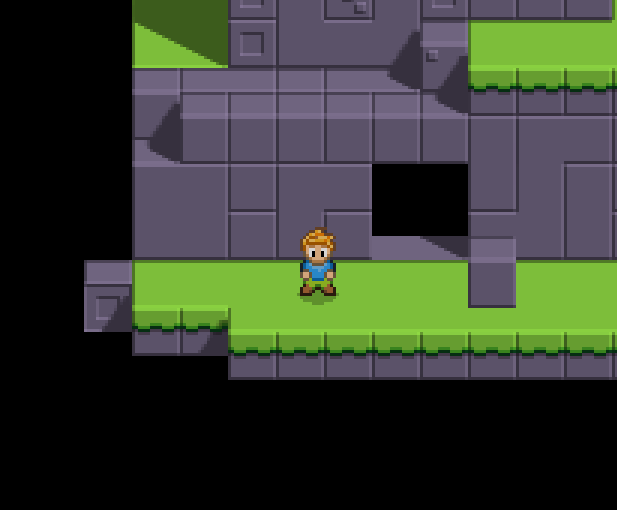
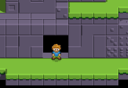
So, the obvious first step is to use orthographic projection and slap an arbitrary top-downish rotation to the camera. As I was making the very first rendering code for the game, I thought that since I wanted a cube take 16 pixels for its side and 8 pixels for its top, the camera angle should be 30 degrees. You know, because 30 is half of 60, right?
Well, I did that, executed the code, and… It looks like a thing! It looks better than the perspective projection, but after scrutinizing it a bit more, the quality isn’t all that good.
Hmm, the player looks squished, and so does pretty much everything. After randomly adjusting each and every parameter of the viewport and the camera, I took a deep breath, dug up my old university notebook and a pen and sat down on my couch to draw the situation.
Step 2: Camera angle
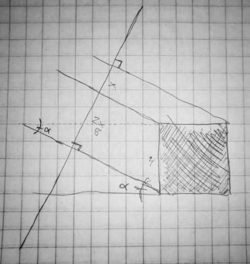
(I’ve drawn this exact image a billion times.)
Trying to wake up the neurons that once were responsible for getting me through my math courses, I jotted down multiple versions of this same idea and tried to find the perfect angle. Looking back, the math here is obvious, but back then, I was rather rusty.
I kept coming back to 30 degrees, because it made sense in totally non-sensical way. Finally, I got it.
angle = atan(x / 2x)
That is, if the cube is equally sized on all its dimensions (e.g. 16 pixels), its side must take 16 pixels on the view plane nad its top must take 8 pixels. The tangent of the angle is thus 0.5 (= 8 / 16), and so the angle is 26.565 degrees (and change).
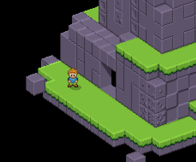
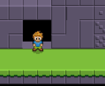
Okay, cool, wow. I was probably shaking at this moment as I booted up my PC and changed the camera angle. Boom.
It’s a tad better, but everything’s still a bit squished.
Step 3: Viewport scaling
As the camera is now rotated so that the cube’s top takes exactly half of the pixels (vertically) of the pixels of the cube’s side (e.g. 8 VS 16 pixels), the cubes are projected correctly.
The problem is that even though the cube’s side VS top relationship is now correct, the cube is not taking 24 pixels on the screen. Back to the notebook, I jotted down some math and noticed that the result is about 21.5 pixels. Well that’s no good.
But wait. What’s 21.5 divided by 24? It’s about 0.896. Could it be…
I took my calculator and typed cos(atan(0.5)) and boom: 0.8944.
That looks close enough.
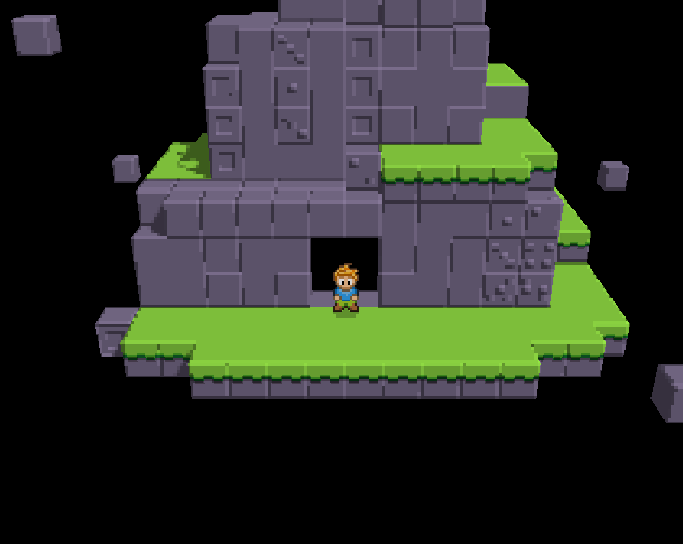
So, I took my viewport, which is has a “world size” of 60 x 36, and squished it vertically by multiplying its height by the 0.8944. As the result of this viewport is scaled to fit the whole screen, the pixels are “streched” vertically to equal to the actual pixels.
There we go! Pixel-perfect 3D to 2D projection achieved!
Pixel-perfect upscaling
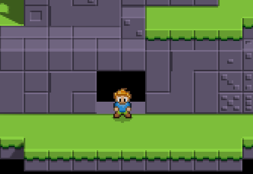
Now that the projection is handled, it’s rather simple to achieve the upscaling. The game displays each in-game pixel as 3x3 group of pixels on the screen. This is achieved by rendering the game world on a small framebuffer, which is then upscaled by rendering it to a full-screen quad.
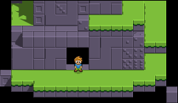
In the above image is the result of the framebuffer right before it’s upscaled and rendered on the full-screen quad.
What is actually being rendered?
This is a topic for a whole ‘nother post, as there’s so much more going on in there!
In a nutshell, the rendering pipeline consists of a deferred renderer and a forward renderer. The deferred context is used for the majority of stuff, such as level geometry and 3D sprites. The forward context is used for unshaded and blended sprites, such as some bright particles.
As a peculiar sidenote, the deferred context is also used for blended sprites - something which is rather uncommon since deferred contexts do not support blending. However, in this kind of game, sprites can have a semi-transparent, static drop shadow, which is used to only darken the color below it. It’s not a real shadow and does not look correct in lighting sense in all cases, but for the purposes of this game, it works.
Conclusion
I hope I’ve shared enough secrets about camera projection so that there’s no mystique going around it anymore. It’s been a path of trial and error, and it has taken multiple rewrites until I got it exactly where I wanted it to be. Chances are your game demands something different and will have its very own obstacles, though.
In the upcoming posts, I’ll try to dive into the lighting system, as well as some more gameplay-related parts of the engine, like how the game is ultimately data-driven and encounters can be scripted in JSON.
Until next time!